Tutorial 10: Speed Test
Just like the Temperature Tower, we can use SynthBlocks to test how fast your printer can go before quality drops. In this tutorial, we'll build a tower that increases the print speed as it grows taller — a quick way to find your printer's sweet spot.
What you'll learn
- How to use the Set Speed block to control feedrate (F-values) in G-code
- How to ramp speed based on height using Map Range and
normZ - How to create a parametric speed calibration test
Prerequisites
- Completion of Tutorial 9 is recommended.
Step 1: Define your variables
We'll expose the speed range and tower height as viewport sliders.
Set Variable
Interactive preview is available in the interactive reader.
Step 1
Create three variables
Add three Set Variable blocks to the top of your Path Group:
- startSpeed =
1000
Enable Show in viewport on each one.
Step 2: Centre on the build plate
Translate
Interactive preview is available in the interactive reader.
Step 2
Add a Translate block
Drag a Translate block below the Set Variable blocks.
Set X to Bed Size X / 2 and Y to Bed Size Y / 2.
All remaining blocks go inside the Translate body.
Step 3: Add the For Z loop
For Z
Interactive preview is available in the interactive reader.
Step 3
Add For Z
From the Structure category, drag a For Z block into the Translate body.
Set Start to Layer Height (the printer-setting block), End to the variable testHeight, and Step to the Layer Height printer-setting block.
Step 4: Set Speed with Map Range
Inside the loop, we'll set the print speed before drawing each layer. The speed ramps from startSpeed at the bottom to endSpeed at the top.
Set Speed
Interactive preview is available in the interactive reader.
Step 4
Add Set Speed
From the Process category, drag a Set Speed block into the For Z body.
Map Range
Interactive preview is available in the interactive reader.
Step 5
Map normZ to Speed
- Drag a Map Range block into the Value input of the Set Speed block.
Step 5: Draw the tower cross-section
We'll draw a circle for each layer and advance the nozzle upward.
Circle
Interactive preview is available in the interactive reader.
Step 6
Add a Circle
From Geometry, drag a Circle block after the Set Speed block (still inside For Z).
Set Radius to 25.
Step 7
Add Travel (Relative) Z
Drag a Travel (Relative) Z block after the Circle (still inside For Z).
Set Z to the Layer Height printer-setting block.
Complete block program
Full program — Tutorial 10
Interactive preview is available in the interactive reader.
Final block structure
| # | Block | Where | Values |
|---|---|---|---|
| 1 | Set Variable startSpeed | Path Group | 1000 · Show in viewport |
| 2 | Set Variable endSpeed | Path Group | 5000 · Show in viewport |
| 3 | Set Variable testHeight | Path Group | 50 · Show in viewport |
| 4 | Translate | Path Group | X = Bed Size X / 2, Y = Bed Size Y / 2 |
| 5 | ↳ For Z | Inside Translate | Start = Layer Height, End = testHeight, Step = Layer Height |
| 6 | ↳ Set Speed | Inside For Z | |
| 7 | ↳ Map Range | Speed Value | In 0–1, Out startSpeed–endSpeed |
| 8 | ↳ Variable | Map Input | normZ |
| 9 | ↳ Circle | Inside For Z | R = 25 |
| 10 | ↳ Travel (Relative) Z | Inside For Z | Z = Layer Height |
Outcome
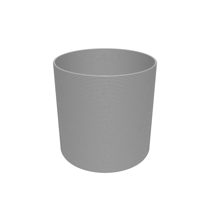
You have created a speed test tower. The bottom will print slowly and cleanly; the top will print fast and might show ringing, underextrusion, or rounded corners. Inspect the print to find the fastest speed your printer can handle without visible quality loss.
Load this tutorial
Interactive preview is available in the interactive reader.
Interactive preview is available in the interactive reader.
What's Next
Tutorial 11: Grid Pattern — Learn to multiply shapes across the build plate using the Grid Array block.